|
|
|
|
|
|
|
|
|
|
INTRODUCTION
Passive imaging systems operating in
the millimeter wave (MMW) band have seen intensive research and
commercial development over the past two decades. The main
motivation for these efforts is the potential capability for passive
MMW imaging to provide effective solutions for tasks, which
currently can not be readily addressed. Example applications are
security screening of people, aircraft landing systems to mitigate
the effects of adverse weather conditions and airborne dust on a
pilots vision, collision warning systems to alert aircraft at
night-time or in bad weather conditions of nearby mountains,
buildings etc., aerial fire-fighting for forest fires where smoke
clouds obscure the accurate deployment of water and fire-fighting
chemicals.
Passive MMW imaging
systems have the advantage of reasonably high spatial resolution
combined with relatively small antenna sizes; may be covertly
deployed as they do not emit any artificial radiation and present no
health concerns as there is no emission of radiation.
An effective antenna
for MMW imaging was invented more than 30 years ago and operates on
the principles of free-wave to surface-wave transformation with a
suitable electrodynamic structure. Such diffraction antenna could
be realized by positioning a planar dielectric wave-guide (PDW)
within the near-field region of a two-dimensional scattering
diffraction grating (DG). The antenna also contains some additional
waveguide elements to provide focusing and transmission of the
electromagnetic waves into the radiometric receiver input. Due to
the dispersive properties inherent to this electrodynamic structure,
a multi-beam antenna pattern can be formed along one coordinate of
the antenna. When the antenna is uniformly rotated these beams are
scanned to form an image. High frame rate passive MMW imaging can be
realized without requiring variable-polarity linear acceleration of
mechanical components of the system; unlike most imagers, which
utilize flapping mirrors.
When compared with a 2D
matrix of receivers, the main advantage of the diffraction antenna
architecture for a passive MMW imaging system is cost. A single wide
band MMW LNA (Low Noise Amplifier) and a single MMW mixer are
required; MMW imagers with multiple receivers require an LNA and MMW
mixer for each receiver. These high-frequency components, which
dominate the bill of materials and result in high costs for current
MMW imaging systems. As with all passive MMW imaging systems, the
limiting factor is the Noise Equivalent Temperature Difference (NETD)
for a single spatial element of the captured image. This NETD is
linked to the antenna rotation speed and therefore the frame rate at
which imagery is captured. Therefore, the main criteria fixing the
frame rate is decided by the acceptable image quality for the
envisaged application.
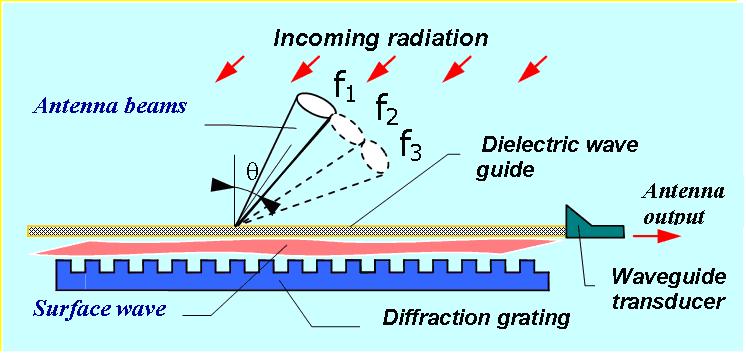
The scanning antenna is based on the transformation of free electromagnetic waves into surface waves, which are guided modes of the dielectric waveguide present in the electrodynamic structure. Figure 1 shows the structure of the open electrodynamic system in a one-dimensional variant. The free electromagnetic plane wave passes through the planar dielectric waveguide, and is scattering on the diffraction grating. The parameters of the open electrodynamic structure are selected, such that, the radiation, which is entering from certain spatial angle, is transformed into a guided wave in the planar dielectric waveguide, which serves to transport electromagnetic waves to the antenna output flange.
In receiving mode, the dispersive antenna is only sensitive to radiation incident at particular angles; these angles are determined by the frequency of the radiation. As a result, the antenna forms one beam of the directional multi-beam pattern per selected frequency band. In transmitting mode the inverse transformation occurs. This dispersive property of the electrodynamic system of the antenna is expressed only along one direction, which is orthogonal to the ridges of the DG. In another plane the dispersion characteristic is absent and the antenna has a single beam at each frequency. The beam width is defined by the size of the receiving aperture along grating vector and by the centre frequency of the signal. Since the angular direction along the direction of the grating vector of each beam is unequivocally associated with the corresponding frequency, if the position of the antenna at any point during its unidirectional rotational motion is known, then the two dimensional position of the beam can be ascertained at any instant. In this way two dimensional passive MMW images can be captured by the diffraction antenna.
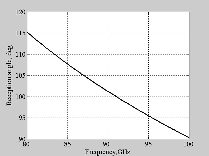
Figure 1: The structure of open electromagnetic system of the diffraction type antenna; f1< f2< f3. The parameters of planar dielectric waveguide and diffraction grating are connected to the angle of incident radiation. As the result dispersion characteristic of the antenna is formed, example of which is presented in Figure 2.
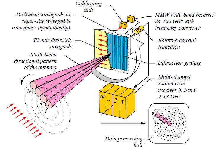
Figure 2: The angle-to-frequency dependence for the designed W-band open electrodynamic structure (angle is calculated relatively to the PDW plane). The antenna system consists of a planar dielectric waveguide, 2D diffraction grating placed under the dielectric waveguide at some distance, and also a horn-parabolic transducer used for connecting the planar dielectric waveguide to a hollow metallic waveguide with an output flange. The main principals of the antenna are, of course, reciprocal, so active systems emitting a wide-band noise signal are possible. By sweeping a continuous wave signal or using pulses, FMCW or pulsed radars can also be realized. OBSERVATION METHOD The main peculiarities of the scheme of passive multi-beam MMW imaging system with circular space observation are shown in Figure 3. The system is based on the principle of multi-beam antenna pattern formation through the effect of frequency beam splitting in antennas with an open electrodynamic system. Unidirectional circular rotation of the antenna beam pattern around the rotating axis is used to form 2D contrast imagery. A linear set of N beams is formed simultaneously in the space domain, with each of the beams is moving in a circular trajectory as about the central axis. The formed image is circular in aspect and is combined from concentric circles with different at radii, each of which is the trajectory of a separate beam. Due to peculiarities of the planar type diffraction antenna, the main elements of which have a planar design and a small thickness and low weight, the antenna has the capability for rotation with relatively high speeds, exceeding ten revolutions per second. Each complete antenna revolution corresponds to one new-formed complete image.
Figure 3: Block-scheme of multi-beam MMW imaging system with rotating space observation method on the base of planar diffraction type antenna The input low noise MMW LNA is located on the rotating platform attached to the antenna unit and operative calibration elements. The received signal, after amplification and frequency down conversion to an intermediate frequency band, passes through the rotating coaxial transition into the static part of the apparatus, where radio frequency and low frequency analog components are located. Together these form a set of separated receiving channels (bands) with a square-law detector in each channel and a multi-channel ADC with data acquisition system. For the tasks of short distance observation, an additional non-rotating lens is placed before the rotating antenna unit with the aim of focusing the beams at the selected distance. As the result of different circular trajectory diameters, the beams located at the central part of an image provide greater temporal overlap than peripheral beams, due to the differences in the linear velocities of the beams. A consequence of this is that a greater integration time can be applied for beams at the central part of the image, providing better radiometric resolution for these beams and a better quality image. One evident peculiarity of the discussed observation principle is the polarization vector rotation for received radiation as the grating rotates. This effect occurs because the surface wave exists only for p-polarized incident waves. For some observation tasks with a scenery consisting of non-polarized or weakly-polarized radiating objects, for example, the case of people screening, or in the case of remote sensing of the ground from an aircraft at near nadir directions, the polarization dependence of brightness temperature of the receiving signal is negligible, or could be taken into account at image data processing.
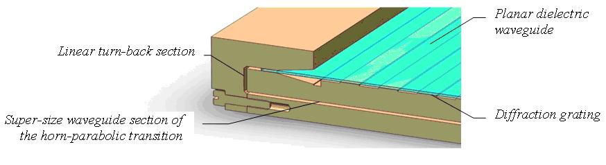
TECHNOLOGY As the result of research, the diffraction and horn-parabolic sections of the antenna both have been developed on the basis of a polymer material suitable for structural component fabrication and providing low antenna weight. To ensure a high-level conductivity of the walls of the horn-parabolic transition and diffraction grating, vacuum-plasma technology is applied to coat the polymer material with a thin copper film. The planar dielectric waveguide is fabricated from a sheet of dielectric material with a calculated thickness by use of plain mechanical polishing technology. The dielectric waveguide is located at a specific distance from the periodic structure of the diffraction grating and is linked to it by the diffraction field. The distance between the grating and the waveguide is selected during the adjustment process and may be changed slightly at the course of adjustments in order to create the given amplitude and phase distribution of the electromagnetic field in the aperture. The diffraction grating is realized as a set of combs with conductive surfaces. The antenna unit is realized in two layers: in the first layer, the diffraction grating is formed on the outer surface of antenna body; in the second layer, a horn-parabolic transition is realized on the base of a super-sized waveguide section; in such a way, active loss is reduced by minimizing the passing wave interaction with wave-guide surfaces. First and second layers of the antenna are connecting by means of linear waveguide turn-back section (two 90 deg. linear turn sections). The antenna has a standard WR10 output flange at the end of the horn, collecting receiving energy inside the horn-parabolic transition. The cross-section of two-layer diffraction type antenna presented at Figure 4.
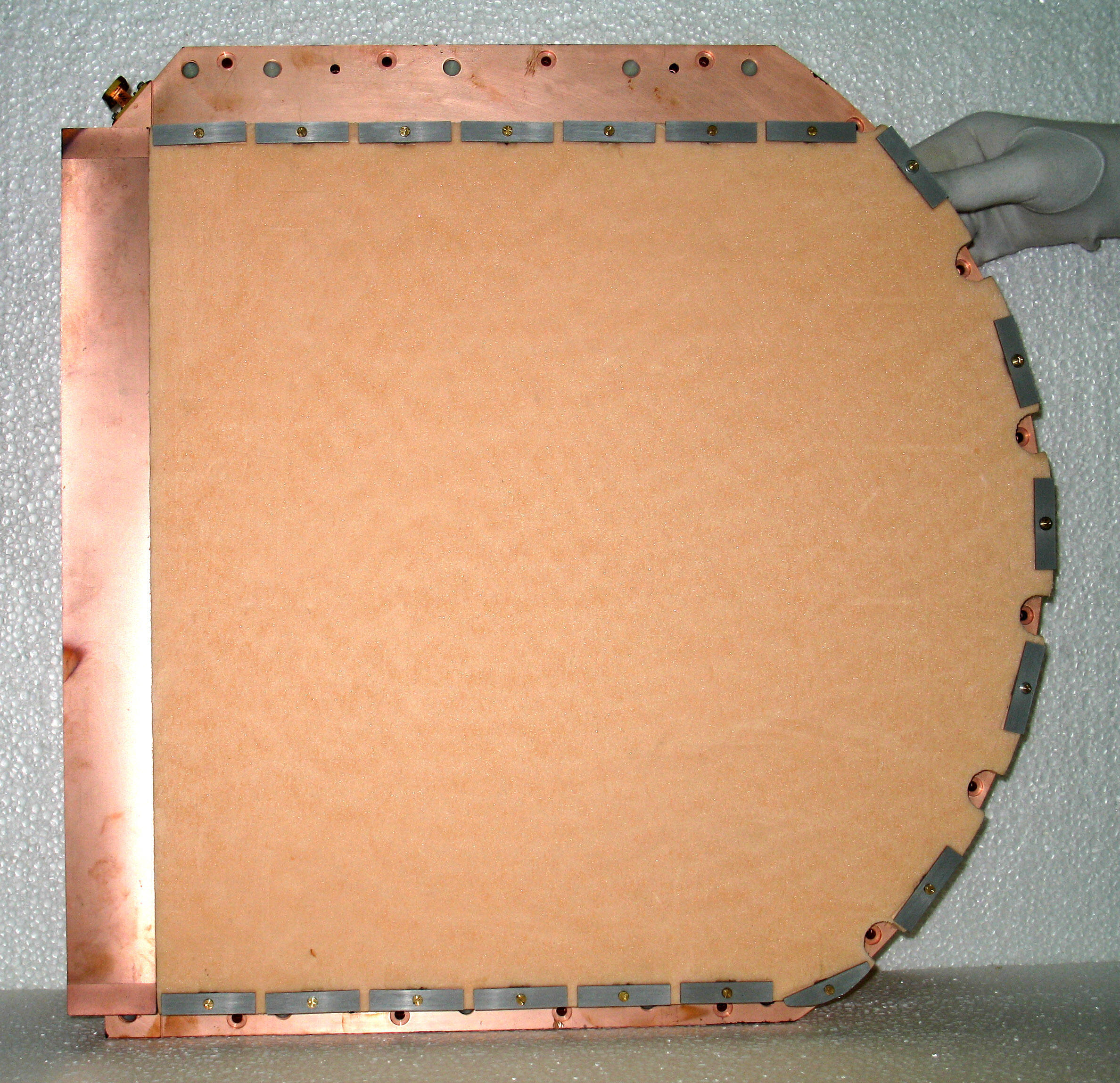
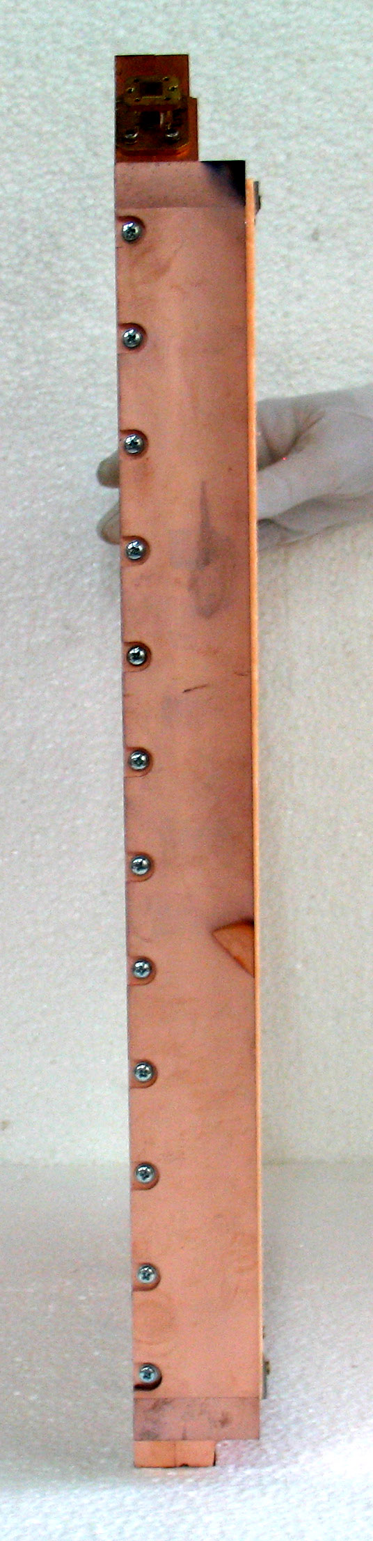
Figure 4: Cross-section of diffraction type antenna The planar dielectric waveguide is precisely located under the diffraction grating by means of a supporting sheet constructed from a low loss radio-transparent material. A general view of the antenna is presented in Figure 5.
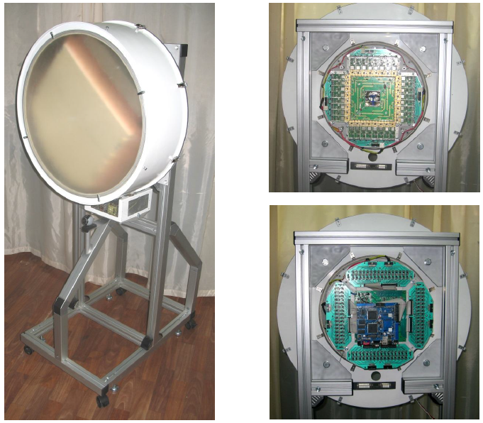
Figure 5: Photographs of the developed diffraction type antenna, front view (left) and side view (right) The imaging system has axial construction for its scanning unit, which is fixed on a stand, and external image processing unit based on a standard PC station. The antenna platform is precisely balanced to avoid dynamic mechanical moments in the course of rotation. The front view of the multi-beam imaging system with non-rotating focusing lens fixed at the front cover is displayed in Figure 6 (left). The rear view of the system without covers at the level of multi-channel microwave receiver is presented in Figure 6 (right top), and at the level of the multi-channel data acquisition unit in Figure 6 (right bottom).
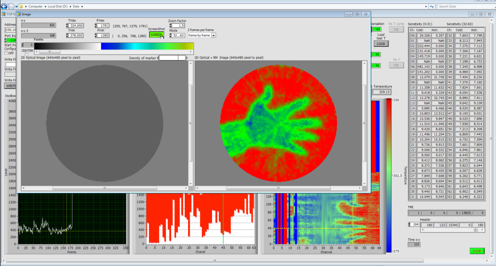
Figure 6: Front view of the 64-beam imaging system with non-rotating focusing lens fixed at the front cover (left). Rear view of the system without lids at the level of multi-channel microwave receiver (right top), and at the level of multi-channel data acquisition unit (right bottom) Two kinds of software modules with appropriate interfaces were developed for optimal realization of the tasks of 1) the system adjustment and debugging and 2) system images forming and storing. First kind software module was developed on the base of LabView platform. It can show output signal of any channel of the receiver in oscilloscope mode, all channels outputs presentation in their min/max amplitudes inside the ADC dynamic range, presentation of the channels levels after their signals transformation to the same absolute temperature scale. This module also provide abilities to MMW images formation and visualization and recording, rotating speed control, radiometric sensitivity of the channels calculation and presentation at real time mode, color palette adjustment and many other functions. It also could represent in parallel MMW and optical images of the scene at small rotation speed of the antenna. The main view of the developed LabView interface is presented below.
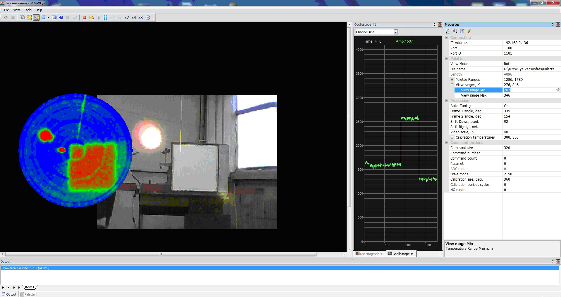
Second software module was developed on the base of VisualC++ platform and is intended mostly for MMW and optical real time images formation, visualization and recording/playing. It has minimal set of functions for debugging and adjustment of the hardware. The main view of the developed VisualC interface is presented below.
It needs to be mentioned that on the base of dispersion properties of the diffraction type electromagnetic structure several type 2D flat antennas may be developed: non-scanning, electrically beam scanning (due to frequency sweeping) and electro-mechanical beam scanning, which may be utilized at different-type radio systems. Click at the button below to see more about already developed antennas ready for implementation.
CONCLUSIONS The concept of a passive MMW imaging system built on the basis of a multi-beam scanning diffraction type antenna has been realized and tested at the W frequency band. Due to the tendency of continued miniaturization of ultra-high frequency and microwave components via integrating technologies, cost effective and low mass movable or portable imaging MMW systems for indoor and outdoor observations could be developed in the near future, operating by the discussed principals of the passive MMW imaging system.
|
|