|
|
|||||||||||||||||||||||||||||||||||||||||||||||||||||||||||||||||||||||
|
|
|
||||||||||||||||||||||||||||||||||||||||||||||||||||||||||||||||||||||
|
During realization of the P389
STCU
project a lot of measurements of the system parameters
was provided. The main results of these measurements are presented at the
Table.
Parameter
Value
Antenna aperture size: H-plane
E-plane
400 mm
420 mm
Beam waist at 3 m distance:
H-plane, level -3 dB
E-plane, level
-3 dB
26 mm (91 GHz)
33 mm (91 GHz)
Effective beam width at the level -3
dB at far field zone, deg.
0,4
(91 GHz)
First side lobe level of a beam
-18 dB (91 GHz)
Antenna gain
44 dB (91 GHz)
Active loss of antenna
3,2 dB (91 GHz)
Beam efficiency measured for
radiating area 75 mm x 65 mm (E x H)
0,71
(86 GHz)
0,68
(91 GHz)
0,64
(98 GHz)
Sector of viewing angles (from
rotating axis), deg.
1-19 (+/- 9)
Antenna rotating speed
1 - 8 rps (2 frames for one revolution)
Operational frequency band
84-100
GHz
Number of beams (receiving channels)
64 (32 for single frame)
Radiometric sensitivity of a
channel at 4 rps:
- for central beams
- for outer beams
1 K
2,5 K
Power consumption of scanning unit (without PC
station), 220 V, 50 Hz
105 W Inside the
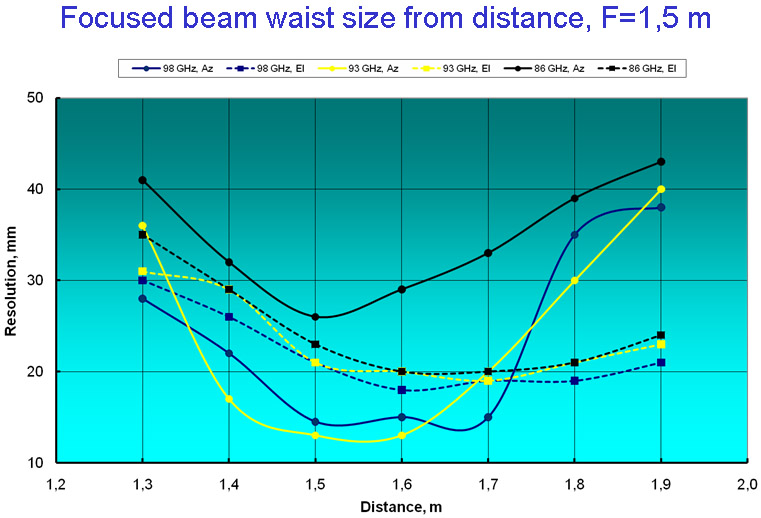
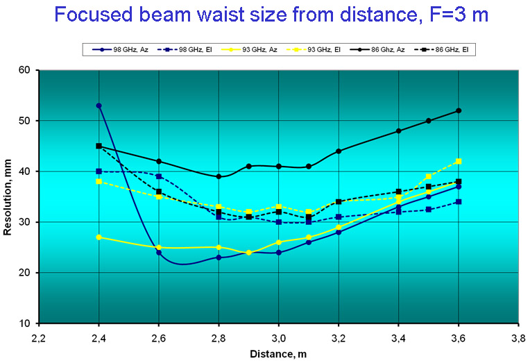
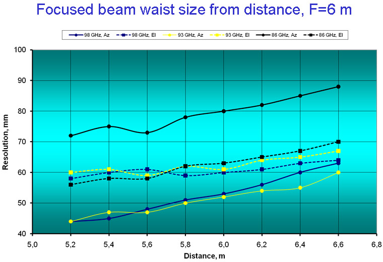
sector of viewing angles antenna beam is focusing on the plane of
view at the specified distance due to replaceable dielectric lens.
The best focusing features were obtained for these distances
selected as 1,5 m; 3 m; 6 m and were reported approximately as 1/100
from the focal distance. For distances longer and shorter than the
specified focal distance spatial resolution (beam waist) is slowly
degraded forming a "dilative tube". Real behavior of spatial
resolution from distance and frequency for specified focal distance
(lens) are presented at the next graphs.
Several
additional improvements seem could be applied to the system due to
separate step-by-step improvements of the antenna and the receiver
unit. Estimates for possible win due to such steps are listed below.
Abilities of the W-band passive scanner improvement
Antenna parameters improvement:
- active loss reduction due to
low-loss material
for planar dielectric
waveguide
Receiver Noise Figure improvement:
~ 1 dB
Total Signal/Noise win
due to all steps for non-cooling LNA ~ 5,4 dB (3,5 times)
Additional improvement due to receiver effective temperature reduction:
~ 3 dB
Total Signal/Noise win due to all steps for cooling LNA .......~ 8,4 dB (7 times)
|
|||||||||||||||||||||||||||||||||||||||||||||||||||||||||||||||||||||||